
The screw is the most frequently used and most versatile machine and fastening element, manufactured and standardized in a wide variety of forms. Depending on the size and type of thread, a screw can precisely move small and big objects, carry tiny and enormous loads, and is, in most cases, exchangeable.
These features are mainly due to the screw’s thread design.
So, in this article, we will get a glimpse into the most common screw threads with their terminology, along with their uses and standards.
Thread Design Approach and Manufacturing
The idea behind a screwed connection is based on a simple wedge mechanism, like the one we use to keep an open door in place. When pushing a door wedge under the door, the door is pushed upward, but the wedge itself is pushed against the floor.
The resulting frictional force between the floor and the wedge keeps the door in place.
Now, we take that wedge and bend it along a helix winding around a cylinder, et voilá! we have a screw thread. And, instead of pushing our wedge against the door, we now turn the cylinder to create forces along the axis of our thread.
Design
This basic design has a huge number of possible applications. Hence, a distinction is made depending on the function: Mainly fastening screws for the production of clamping connections and movement screws for converting rotary movements into longitudinal movements or for generating large forces.
Also, sealing screws are used, e.g., for closing fillings and discharge openings.
Screw Material
Considering their relatively complex shape and high loads, generally, threads are made from steel due to their strength and relatively inexpensive cost. However, screws and fasteners can also be produced from stainless steel, brass, titanium, and a wide range of other metals, depending on the application.
Depending on the production amount, methods like casting, rolling, or machining by cutting and grinding are used.
Basic Screw Thread Terminology
The below illustration (figure-1) gives an overview of the basic terms used to describe screw threads. As the nut is screwed on the bolt clockwise, it is pushed against the part shown in blue resulting in the desired clamping stress or the load distribution.
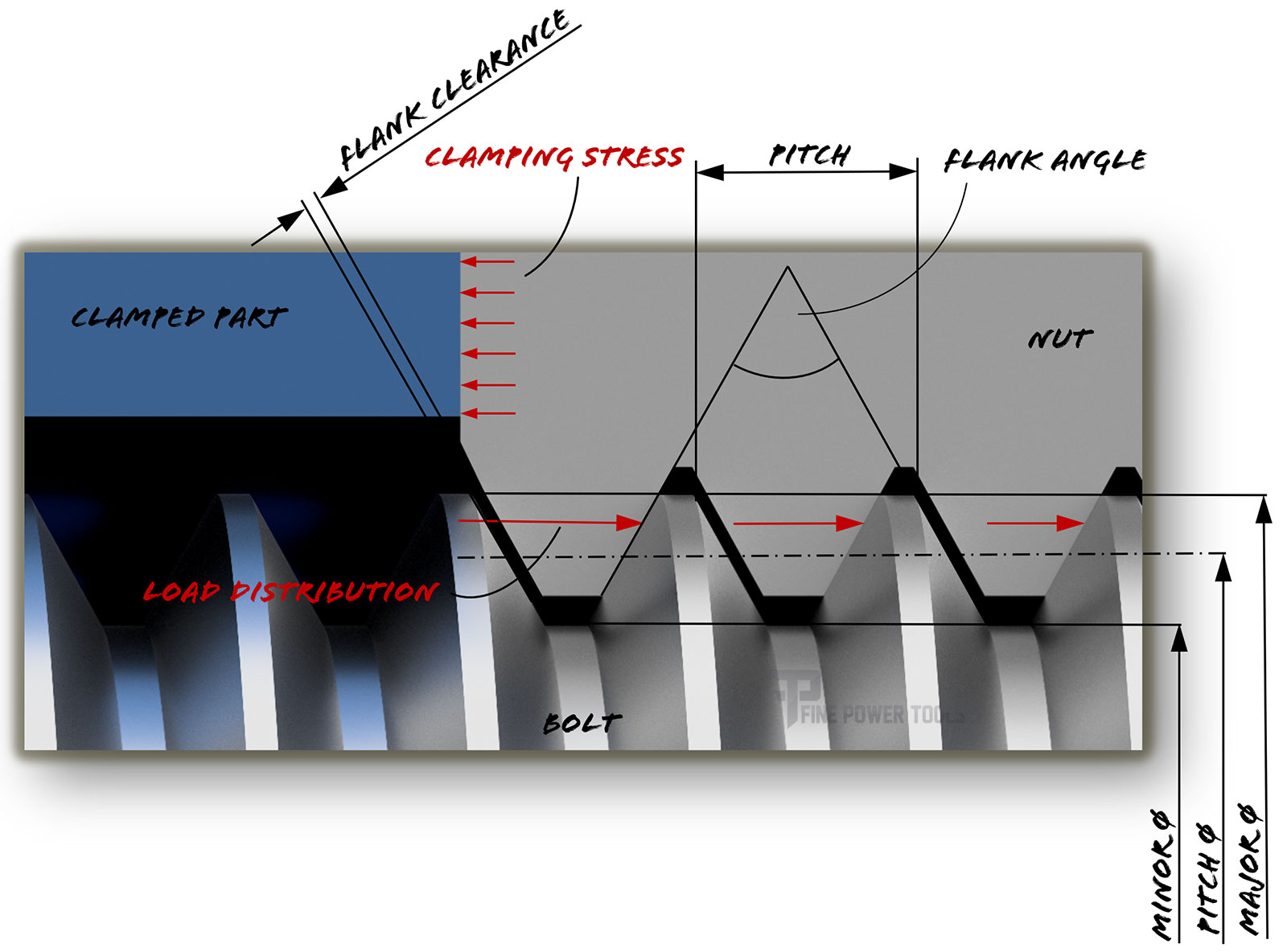
Fig-1: Parts of a screw thread.
- The major diameter describes the largest diameter of the thread. Say, if you have a “Metric 10 machine screw”, the major diameter will measure 10mm, likely a tiny bit less to ensure fastening with a nut.
- The minor diameter is the smallest diameter in the “valley” of the thread. That value is used by engineers for calculating the pull-out strength of the screw.
- The pitch diameter is the mean between the major and minor diameter and is used to calculate the maximum possible torque a screw can carry.
- The pitch is the distance between the “mountains” or the valleys. For finer threads, the value is small, and vice versa for coarser ones. A 1mm pitch means that after one complete revolution, the screw has moved 1mm along its axis. Therefore, this value has a big impact on the movement screws used, e.g., in turning machines.
- The flank angle affects the slope of the “mountains” and, therefore, the width of the valleys.
- The flank clearance is a small gap due to production tolerances to ensure that the nut and bolt threads fit. If you’re working on an older turning machine, you will feel a tiny bit of play when moving your tool back and forth. This is due to the flank clearance.
The manufacturing tolerances for some of these values are pretty tight, too. The allowed deviation basically increases with pitch size and internal tolerance class of the standard.
For example, the internal and external thread diameters of a general purpose Ø1mm V-shaped thread have a general tolerance field of 0,032 mm.
- The major diameter describes the largest diameter of the thread. Say, if you have a “Metric 10 machine screw”, the major diameter will measure 10mm, likely a tiny bit less to ensure fastening with a nut.
- The minor diameter is the smallest diameter in the “valley” of the thread. That value is used by engineers for calculating the pull-out strength of the screw.
- The pitch diameter is the mean between the major and minor diameter and is used to calculate the maximum possible torque a screw can carry.
- The pitch is the distance between the “mountains” or the valleys. For finer threads, the value is small, and vice versa for coarser ones. A 1mm pitch means, that after one complete revolution, the screw has moved 1mm along its axis. Therefore, this value has a big impact on the movement screws used e.g. in turning machines.
- The flank angle affects the slope of the “mountains” and, therefore, the width of the valleys.
- The flank clearance is a small gap due to production tolerances to ensure that the nut and bolt threads fit. If you’re working on an older turning machine, you will feel a tiny bit of play when moving your tool back and forth. This is due to the flank clearance.
The manufacturing tolerances for some of these values are pretty tight, too. The allowed deviation basically increases with pitch size and internal tolerance class of the standard.
For example, the internal and external thread diameters of a general purpose Ø10mm V-shaped thread have a general tolerance field of 0,032 mm.
Screw Thread Profiles and standards
The shape of the thread itself has a big effect on the function of the thread.
Depending on the purpose of the threads, we can categorize them into three types.
- Fastening threads
- Movement threads, and
- Special-purpose threads
The below figure (fig-2) shows common thread profiles for a Ø10mm major diameter.

Now, let’s take a look at each type of screw thread in detail.
Fastening Thread
- V-shaped: Standard fastening thread in mechanical engineering. Available in different pitches, the pitch angle stays a constant 60°. The exact profiles are defined in the ISO 68-1 for metric threads and in the UNC and UNF for imperial threads.
- Whitworth: Used within the imperial system but also used for connecting pipes and fittings. In countries using the metric system, the pitch angle is a constant 55°. It was one of the first threads to be standardized nationally. Today, it’s referred to as the British Standard Whitworth (BSF) standard in ISO 7-1 and 228-1.
- Self-tapered: A thread that can tap its thread as it is driven into the material, commonly used for screws inserted into wood or plastics.
Self-tapered threads for sheet metals are also available and standardized by ISO 1478.
Movement Thread
- Trapezoidal: Their large pitch relative to the diameter allows for carrying high axial forces and is therefore used for lead screws on lathes or threaded spindles on vises.
For metric systems, ISO 2901 governs the thread shape, and ASME B1.5 for imperial units. The flank angles are 30° or 29°, correspondingly. - Knuckle thread: Due to its low notch effect and large clearance, it’s used for rough surfaces like coupling spindles for railroad cars. It is governed by the DIN 405 standard with a flank angle of 30°
- Saw thread: The saw-like shape results in higher load-bearing capacity for one-sided loading, like spindles of presses and collets for lathes.
For imperial threads (ASME B1.9), the flank angle is 45°, but the pressure angle (the slightly slanted area used to apply the axial load) is 7°. For metric threads (DIN 513) the flank angle is 30° and the pressure angle is 3°.
Special Threads
Some special threads not shown above include multi-start threads and tapered threads.
- Multi-start threads have more than one thread to increase the support surface, which increases the maximum allowed load. Also, the flank clearance is reduced, which contributes to making the entire system more precise.
- Tapered threads find application for sealing screws.
The pitch diameter of these threads is not constant but decreases as thread length advances. This allows for wedging the threads of nut- and bolt-thread together.
In conclusion, threads are a powerful tool used for basic connections to sophisticated machinery due to their versatility, exchangeability, and powerful connections.
Back to Contents

Dan Miller is a professional toolmaker with extensive experience in the metalworking and tooling industry.
An avid DIY enthusiast and passionate hobbyist woodworker, Dan shares his expert knowledge here.